The following text is meant as a refresher of basic networking principles. If you have taken the NSWI141 (Introduction to Networking) course, you should know everything mentioned in this text. If you have not taken NSWI141 or similar, the following text will provide you with absolute minimum of knowledge needed for lab 11.
Note that the following text contains many simplifications (though they should not contradict actual technical implementation in any way).
We will first discuss how is networking divided into layers, we will briefly talk about addressing and finish with overview of the actual communication (from the end-point side).
Most of the text will cover TCP on top of IP though many of the principles are applicable to other protocols as well. We are assuming IPv4 for practical reasons.
We will use the word packet to denote any data that are travelling over the network as a single unit. We will use it to refer to both physical frames on the Ethernet as well as to IP packets and TCP segments for simplification.
Layers ⚓
To simplify implementation and configuration of networking, concept of several layers is used.
The bottom layer is the physical one (TCP/IP model calls it the link layer).
This layer is responsible for communication between machines on the same segment:
either two directly connected computers or multiple machines connected to the same
(physical) wire.
You can think about Ethernet (using e.g. RJ-45 connectors) on this layer.
Ethernet uses MAC addresses (e.g. 54:e1:ad:9f:db:36) to distinguish individual
members of the communication.
Above the link layer is the internet layer. This layer is responsible for communication of any two computers. For the delivery it uses the link layer below but adds logic for routing the traffic to greater distances. Most of the hard-work on this layer is done by routers that are connecting different networks. This includes your private home network with a WiFi router as well as connectivity between backbone networks.
IP (or internet protocol) is the protocol used on this layer.
It uses addresses consisting of four single-byte values, delimited by a dot
(e.g. 192.168.0.105).
Transport layer is above the internet layer. It is implemented mostly on the end-points (your machine or a smart TV or a cell phone) and uses the internet layer to send the data between the communicating ends (the two machines). This layer takes care of splitting too big packets to be accepted by the internet layer and often takes care of quality of service aspects (e.g. resending packets that were lost).
This layer also often defines which programs are communicating. In this sense, the internet layer delivers the packet to the right machine and transport layer directs to the right program (e.g., a web browser on one side and web server on the other side).
Protocols used on this layer include TCP, UDP or ICMP. Some of the protocols use port numbers to distinguish the senders and receivers. Many of the port numbers are well-known and host a typical applications (e.g., SSH is usually running on port 22 (TCP), web server is listening on 80 or 443 for HTTPS, both are TCP-based).
The top-most layer is the application layer.
This layer defines which data format is used.
For example, for HTTP it defines that the header starts with either GET or POST
(written in ASCII), followed by the requested path, etc.
It relies on the transport layer to deliver the data to the other communicating party.
Protocols on this level include HTTP, SMTP, FTP or SSH.
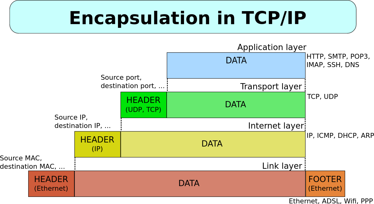
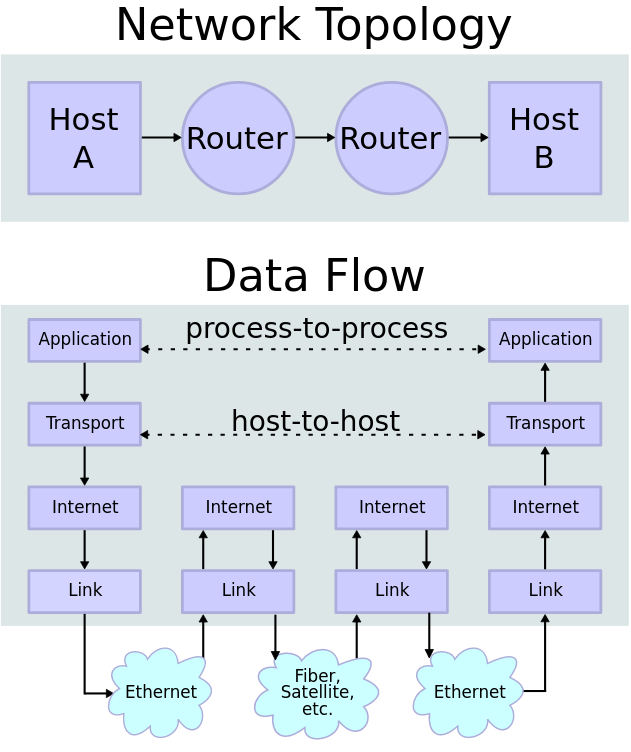
The following pictures from Wikipedia captures this in a graphical form. The first pictures shows how service data (IP addresses, port numbers etc.) are added on each layer, taken from Wikimedia page author David Mudrák (mudrdmz), CC BY-SA 3.0, via Wikimedia Commons. (English translation by us). Second picture illustrating the transfer is from Wikimedia page, author en:User:Kbrose, CC BY-SA 3.0, via Wikimedia Commons.
Addressing ⚓
The basic unit of addressing is the IP address. We often talk about a machine having an IP address but practically the IP address is bound to a network interface (a network adapter).
On the home network, the IP address is typically assigned automagically through the DHCP protocol. Basically, the newly connected machine sends a generic request for an IP address and one machine is designed as a DHCP server that responds with the proper configuration (typically, that will be your home WiFi router).
IP address is unique for each machine (interface) and allows global addressing (see section on NAT for some practical limitations, though). Thus, any machine shall be able to send a packet to any other machine on the whole network (Internet).
The actual routing of the packet can be rather simplistic. We can imagine that end-point machines are always connected to a single router and routers are connected to routers on the higher level. Up to a central router for the whole world. This would create a tree-like structure. Then, to send a packet to its destination, each router would need to know to which direction to send each packet (i.e., whether to a higher level or to a lower level).
Practically, this would mean that any router would need to know information about each machine and its IP address to be able to correctly decide where to send the packet.
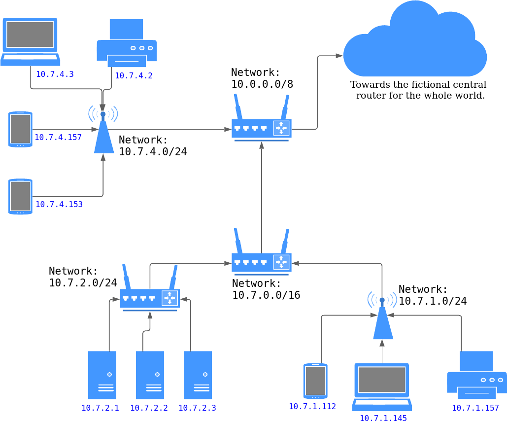
This is rather impractical. Therefore, the machines are organized into smaller networks (subnets) that share part of the IP address. Then, the routers only need to know the direction for the whole subnet, greatly reducing the amount of information to remember.
The subnet is defined by a prefix of the IP address: first N bits of the IP address denotes the address of the whole network. Such system is very practical as it allows nesting subnets and simplifies the routing.
The network is then described as 192.168.0.0/24 where /24 means that
24 bits describe the network, leaving 8 bits to distinguish individual
machines in this subnet.
Then, machines will have addresses of 192.168.0.1, 192.168.0.2 to
192.168.0.254 (special address of all zeros and all ones – in binary –
are used for special purposes).
Note that each machine has to know about the prefix length too to properly
function.
In practice, the network topology is less regular and there are multiple paths between the routers. The routers dynamically adapt their routing rules to send the packets over the fastest path. But the principle of hierarchical division of the IP addresses into subnets still holds.
You can imagine that each continent is a huge subnet, each country a smaller one and on the other side of the spectrum, your home router controls the smallest subnet.
Communication ⚓
The actual communication between two machines can be described in the following
steps.
We will illustrate it on an example of a web browser (running on machine
with IP address 1.2.3.4) connecting to a web server (on 195.113.20.60).
The web browser initiates the connection.
It prepares a packet that has destination set to 195.113.20.60 with port 80
(well-known port for HTTP server).
As the sender, it fills its own address 1.2.3.4 and a free port provided
by the operating system (OS) (here, we will assume port 5678).
The OS running the web browser will deliver this packet to the network card that physically sends it to the nearest router. This router looks at the destination field and sends the packet to the next router.
Eventually, the packet arrives at the destination server at 195.113.20.60.
There, the OS reads the port number and delivers the packet to the application
that is listening on this port (basically, the web server announced
to the OS that it will accept packets coming to the port 80).
The web server processes the request and sends a reply.
The destination will be the original sender: 1.2.3.4 and port 5678.
Using the same process, the packet arrives back at the first machine
(where the browser is running).
The OS already knows that the port 5678 was given to the web browser and
thus it forwards the packet to the browser.
Browser displays the result to the user.
Technically, the communication is initiated with a so-called handshake
where the communicating parties agree on the transfer configuration
(e.g. maximum packet size).
Each packet is then usually confirmed by a short packet sent in the
other direction that informs that the delivery was successful.
Absence of the acknowledgement (often called just ACK) triggers a re-sending
of the packet.
Only when multiple resends are not ACKed, the program announces an error
to some upper layer (e.g. by throwing an exception).
NAT ⚓
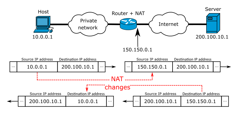
The space of IP addresses is about 2564 big. Practically, we have run out of IP addresses many years ago. To bypass this, you will often encounter a so-called NAT, or Network address translation.
In this configuration, a single machine (typically, a router) hides a whole network under single address. For the outside world, the requests seem to originate from the NATting machine. This machine then takes care of delivering the packet to the right machine behind the NAT.
The disadvantage is that you cannot address the machine behind NAT as they are transparent to the outer network. From the other side, it works well – the machine behind NAT can address any machine in the outer network as the NATting router is transparent too.
On your home network, you are typically hidden behind several layers of translated addresses. It is no exception that your ISP uses two or three of them to save so called public IPs. Your home network adds another layer.
Using NAT divided IP addresses into two groups:
public IP addresses are globally addressable and are needed for machines
providing a service.
Private addresses (such as 192.168.0.0/16) are hidden behind NAT
and it is up to the administrator of each network to use them as he sees fit.
Note that NAT shall not be confused with (and treated as) a security measure and vice versa.
The illustration of the network address translation process is taken from this Wikimedia page, author Michel Bakni, CC BY-SA 4.0, via Wikimedia Commons.
IPv6 … ⚓
… as the (possible) successor to IPv4 that solves not only the problems of not-enough-IP-addresses is not covered in this text.